Diode Production Testing
•Test Instrumentation
•Diode Production Test
•Test System Configuration and Scenarios
•Diode Polarity Known
•Diode Polarity/Orientation Unknown – Component Handler can Turn Device
•Diode Polarity/Orientation Unknown – Component Handler does not Turn Device
• IEEE-488 Bus Operation
•Handler with Capability to Turn the Diode
•Handler without Capability to Turn the Diode
•Switching Multiple Diodes
•Typical Sources of Error
•Equipment List
High-quality single-point pass/fail production testing on packaged diodes is critical to ensure compliance with manufacturers' specifications and to eliminate defective devices before they are shipped. Most types of diodes undergo at least one polarity test and three parametric tests during the final inspection process. While the reliability of these tests is essential to ensuring product quality, it is equally important that they be performed quickly to maintain high production throughput.
Typically, several instruments are required to perform these tests, such as a digital multimeter (DMM), voltage source, and current source. As the number of instruments in the test system increases, however, the overall measurement process becomes slower, reducing test throughput. Coordinating the operation of separate instruments extends the measurement cycle by increasing the amount of bus traffic required. A system configured with a separate DMM and sources also requires substantially more rack space than a system built with all these functions in a single unit.
In addition to higher equipment costs, three separate instruments also mean there are three sets of commands to learn, complicating system programming and maintenance. Using multiple instruments and sources also makes trigger timing more complex and increases triggering uncertainty.
With the advanced digital instrumentation available today, however, diode production test systems may be configured using a single instrument that can source and measure both current and voltage. Such instruments have proven to be highly effective for accurately and efficiently executing diode production tests.
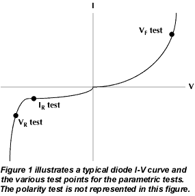
There are essentially four diode production tests: Polarity, Forward Voltage (VF), Reverse Breakdown Voltage (VR) and Leakage Current (IR). Figure 1 illustrates a typical diode I-V curve and test points for the parametric tests.
Polarity testing is often required on many of the newer surface mount diode packages, such as the Small Outline Diode (SOD) package. Such diodes do not automatically orient themselves in the same direction in a component handler, so the polarity of the device must sometimes be determined before beginning the full functional test sequence.
The polarity test is designed to determine the orientation of the diode safely and quickly prior to completing functional tests on the device. The breakdown characteristics of the diode are used to generate an indication of the diode's polarity in one of two ways. A positive current can be sourced through the diode and the voltage measured. A voltage of less than 1V (typically) indicates forward polarity of the diode, while a high voltage indicates breakdown and reverse polarity.
Alternatively, a negative current can be sourced, in which case a voltage measurement less than 1V indicates reverse polarity, while a high voltage indicates breakdown and forward polarity. The choice between these two methods for polarity testing depends primarily on the overall structure of the test program.
The forward voltage (VF) parametric test involves sourcing a specified forward bias current within the normal operating range of the diode, then measuring the resulting voltage drop. To pass the test, the voltage must be within specified minimum and maximum values.
For the reverse breakdown voltage (VR) parametric test, a specified reverse current bias is sourced and the resulting voltage drop across the diode is measured. To determine whether the diodes pass or fail, the measurements are compared to a specified minimum limit.
The leakage current (IR) parametric test verifies the low level of current that leaks across the diode under reverse voltage conditions. This test is performed by sourcing a specified reverse voltage, then measuring the resulting leakage current. Good diodes will produce a leakage current that is less than or equal to the specified maximum value.
Test System Configuration and Scenarios
Figure 2 illustrates a block diagram of a source-measurement unit-based system for diode production testing.
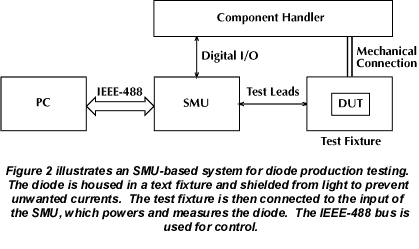
As shown in Figure 2, the diode or diode package is placed in a test fixture and connections are made to the input of the source-measurement unit (SMU), a single diode production test instrument. To prevent the generation of unwanted currents, a text fixture is used to shield the diode from light. Using the IEEE-488 bus for control, the SMU powers and measures the diode. The resulting measurements are then compared to pre-specified limits in the instrument and pass/fail determinations are made.
Output signals from the SMU's digital I/O port are used for interfacing with the handler to initiate diode orientation and/or binning. In this particular example, the instrument is equipped with four digital output lines that can be configured using Standard Commands for Programmable Instruments (SCPI). Depending on how the SMU is programmed, each digital output code conveys a message, such as "part is good," "part is bad," "turn part," etc.
The ability of the SMU to interface directly with the component handler frees the PC during handler control operations. This makes it possible for the computer to download and store test data while a new diode or diode package is being positioned in the test fixture.
Following are three algorithms that describe diode testing under three different scenarios, depending on handler capability and diode package.
The following algorithm describes the operation of an SMU-based diode production test system to perform the measurements described when the polarity of the diode is known prior to functional testing.
- Operator indicates to the PC that a diode production lot is in place and ready for test.
- PC initiates SMU operation over the IEEE bus.
- SMU waits for Start of Test trigger from handler.
- When the first diode is in position, the handler sends a Start of Test trigger signal to the SMU, indicating that the first diode is ready for testing.
- The SMU runs the diode functional tests in the order stored in the source memory, makes pass/fail determinations and saves the data for each test: forward voltage, breakdown voltage and leakage current.
- The SMU sends overall pass/fail code and End of Test signal to handler and sends test data to the PC (operations occur in parallel). (Note: Some SMUs may not have this capability.)
- Repeat Steps 3-6 for remainder of diodes in lot.
- SMU returns to idle state. Operator installs new lot of diodes in handler.
- Repeat Steps 1-8 as required.
Diode Polarity/Orientation Unknown – Component Handler can Turn Device
The following algorithm describes the operation of an SMU-based diode production test system to perform the measurements described when the polarity of the diode is unknown prior to functional testing and the handler can turn the diode end for end.
- Refer to Steps 1–4 of Diode Polarity Known sequence.
- The SMU executes the polarity test. If the diode is verified in forward polarity, the SMU proceeds with functional tests. If the diode is verified in reverse polarity, a signal is sent to the handler to turn the device and return to Step 4 (refer to Diode Polarity Known sequence).
- Once the diode is in forward polarity, the SMU runs the diode functional tests in the order stored in source memory, makes pass/fail determinations and saves the data for each test: forward voltage, breakdown voltage and leakage current.
- The SMU sends overall pass/fail code and End of Test signal to handler and sends test data to PC (operations occur in parallel). (Note: Some SMUs may not have this capability.)
- Repeat sequence for remainder of diodes in lot.
- The SMU returns to idle state. Operator installs new lot of diodes in handler.
- Repeat all steps as required.
Diode Polarity/Orientation Unknown – Component Handler does not Turn Device
This algorithm describes the operation of a diode production test system to perform the measurements described when the polarity of the diode is unknown prior to functional testing and the handler cannot turn the device under test.
- Refer to Steps 1–4 of Diode Polarity Known sequence.
- The SMU executes the polarity test. If the diode is verified in forward polarity, the SMU proceeds with functional tests using forward polarity parameters (see Step 3). If the diode is verified in reverse polarity, the SMU runs tests using reverse polarity parameters (see Step 4).
- The SMU runs forward polarity diode functional tests in the order stored in source memory, makes pass/fail determinations and saves the data for each test: forward voltage, breakdown voltage and leakage current.
- The SMU runs reverse polarity diode functional tests in the order stored in source memory, makes pass/fail determinations and saves the data for each test: forward voltage, breakdown voltage and leakage current.
- The SMU sends overall pass/fail code, diode polarity indicator, and End of Test signal to the handler and sends test data for PC (operations occur in parallel). (Note: Some SMUs may not have this capability.)
- Repeat sequence for remainder of diodes in lot.
- The SMU returns to idle. Operator installs new lot of diodes in handler.
- Repeat all steps as required.
Following are general recommendations for writing a program to set up and execute the diode functional tests. As this procedure indicates, each test setup is stored in a source memory location (SML). For purposes of this discussion, an SMU with a partitioned SML will be assumed. This instrument has storage capacity of up to 100 test set ups (49 when polarity must be determined) in individual SMLs. It should be noted that some SMUs may not have this capability.
Diode functional tests can be executed in various sequences from one trigger over the IEEE bus. The instrument steps through the SMLs without computer intervention, thereby saving IEEE bus time and increasing system throughput. The following guidelines assume that polarity testing is not required.
- Initialize the general purpose instrumentation bus (GPIB) and SMU.
- Set the SMU parameters that will be common to all tests (e.g. autozero, data format, etc.).
- Define the forward voltage test.
- Command SMU to source current: set source range, value and delay.
- Command SMU to sense voltage: set measure range and compliance value.
- Set limit values and digital output bit patterns for each pass/fail outcome.
- Save forward voltage test configuration in SML #1.
- Define the breakdown voltage test.
- Command SMU to source current: set source range, value and delay.
- Command SMU to sense voltage: set measure range and compliance value.
- Set limit values and digital output bit patterns for each pass/fail outcome.
- Save breakdown voltage test in SML #2.
- Define the leakage current test.
- Command SMU to source voltage: set source range, value and delay.
- Command SMU to sense current: set measure range and compliance value.
- Set limit values and digital output bit patterns for each pass/fail outcome.
- Save leakage current test in SML #3.
- Set Trigger mode for handler interface.
- Initiate testing.
- Store data.
Completion of polarity tests prior to functional testing requires some programming changes and additions to the basic guidelines previously listed. The specific changes are dependent on the type of handler used, as described earlier. For either scenario, however, the integration of the polarity test with subsequent functional tests is accomplished using the branching capability of the SMU's source memory location. This capability allows the user to program the instrument to execute different sequences of tests stored in source memory depending on the outcome of the previous test. In this example, execution of functional tests proceeds in different ways, depending on the outcome of an initial polarity test.
Another SMU feature used in these test scenarios is the compliance limit test. For the polarity test, the compliance value of the instrument is set to a level that indicates diode breakdown, and Limit 1 is activated to set a PASS/FAIL condition based on whether the voltage input reaches this compliance setting. This technique allows determination of diode polarity without the time required to perform an actual voltage measurement, thereby increasing test throughput.
The following guidelines assume that polarity testing is required.
Handler with Capability to Turn the Diode
The IEEE bus operation for this configuration is similar to that for testing diodes of known polarity except for the use of additional SMLs and branching.
- SML #1 contains the polarity test, which is a reverse voltage test that is passed if the diode breaks down (i.e., compliance setting is reached), indicating forward polarity. Limit 1 is set for failure when the SMU is not in compliance.
- One of the SMU's four digital output lines is used to indicate to the handler when a diode must be turned to correct its polarity.
- SMLs #2, #3 and #4 are assigned as dummy test locations, needed simply to increment the source memory and trigger counters. These SMLs are executed only if a reverse polarity diode is encountered, i.e., SML #1 (polarity) test results in a FAIL condition.
- SMLs #20, #21 and #22 (or any other three sequential SML locations) hold the functional tests of Forward Voltage, Breakdown Voltage and Leakage Current, which are executed when the SML #1 test results in a PASS condition.
Handler without Capability to Turn the Diode
The IEEE bus operation for this configuration is similar to that for testing diodes of known polarity except for the use of additional SMLs and branching. However, it differs slightly from the previous procedure in its structure and use of digital I/O.
- SML #1 contains the polarity test, which is a forward voltage test that is passed if breakdown does not occur (instrument does not reach compliance), indicating forward polarity. Limit 1 is set for failure when the SMU is in compliance.
- SMLs #2, #3 and #4 are used to store the functional test settings for a diode in reverse polarity and are executed when the SML #1 test results in a FAIL condition.
- SMLs #20, #21 and #22 (or any other three sequential SML locations) are used to hold the functional test settings for a diode in forward polarity and are executed when the SML #1 test results in a PASS condition.
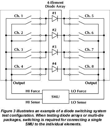
For diode arrays or multi-die packages, switching is required for connecting a single SMU to each of the individual elements. Figure 3 is an example of a diode switching system test configuration. Actual systems can be configured for any number of diode elements and for various electrical specifications.
Note that two, 2-pole relays are used to connect each diode to the SMU. This is done to eliminate error from the voltage drop in the switch and lead resistance. This is particularly important when measuring the forward voltage because the measured voltages are relatively small (millivolts) and the source current is relatively high (milliamps).
To measure the forward voltage of diode #1, close channels 1 and 5, apply the specified current, and measure the resulting voltage drop. Next, perform the breakdown and leakage tests on diode #1 and then open channels 1 and 5. Close channels 2 and 6 to begin testing diode #2. Repeat this procedure for all the diodes.
While conducting production diode tests, there are typically three sources of error: lead resistance, leakage current and electrostatic interference.
Lead Resistance
A common source of voltage measurement error is the series resistance from the test leads running from the instrument to the diode. This series resistance is added into the measurement when making a 2-wire connection (see Figure 4).
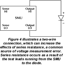
The effects of lead resistance are particularly detrimental when long connecting cables and high currents are used because the voltage drop across the lead resistance becomes significant compared to the measured voltage.
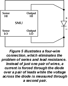
To eliminate this problem, use the four-wire remote sensing method rather than the two-wire technique. As shown in Figure 5, a current is forced through the diode using one pair of leads and the voltage across the diode is measured through a second set of leads. As a result, only the voltage drop across the diode is measured.
Contact Check
Another source of voltage measurement error is damaged, corroded, or otherwise faulty contacts in a test fixture. Some SMUs have a built-in contact check feature that allows quick verification of good connection to the DUT before functional testing proceeds.
Leakage Current
Stray leakage in cables and fixtures can be a source of error in measurements involving very low currents, such as for leakage currents. To minimize this problem, construct test fixturing with high resistance materials.
Another way to reduce leakage currents is to use the built-in guard of the SMU. The guard is a low impedance point in the circuit that is nearly the same potential as the high impedance point to be guarded. Figure 6 illustrates this technique.
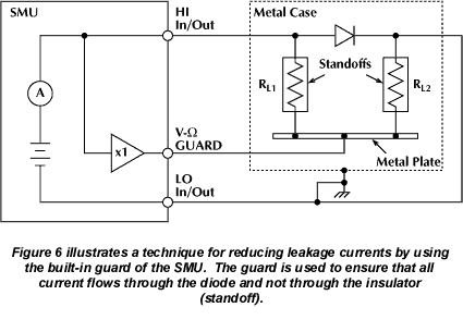
In this example, the diode to be measured is mounted on two insulated standoffs (RL). Guard is used in this circuit to ensure that all the current flows through the diode and not through the standoffs. In general, cable guard should be used when sourcing or measuring currents below 1µA. This circuit is guarded by connecting the V- Guard terminal of the instrument to the metal plate. This puts the bottom of insulator RL1 at almost the same potential as the top. Since both ends of the insulator are at nearly the same potential, no significant current can flow through it. All the current will then flow through the diode as desired.
WARNING! Guard is at the same potential as output HI. Therefore, if hazardous voltages are present at output HI, they are also present at the Guard terminal.
Electrostatic Interference
High resistance measurements may be affected by electrostatic interference, which occurs when an electrically charged object is brought near an uncharged object. To reduce the effect of electrostatic fields, a shield can be built to enclose the circuit being measured. As shown in Figure 6, a metal shield connected to ground surrounds the diode under test. The LO In/Out of the SMU must be connected to the metal shield to avoid noise due to common mode and other interference. This also acts as a safety shield because the metal plate is at guard potential.
The following list represents a possible equipment configuration for conducting a diode production test:
- Keithley Model 2400, 2410 or 2420 SourceMeter instrument, with or without the contact check option.
- PC with KPC-488.2 Interface Card.
- Component handler with test fixture.
- Keithley 7007 IEEE-488 interface cable.
- Custom DB-9 digital I/O handler interface cable (to interface the instrument to the handler).
- Test leads to connect the instrument to the test fixture.
It is important to note that all SMUs may not have the same capabilities as those presented in this article, and that equipment performance and functionality is essential to accurate diode testing. By using one instrument versus several, the testing process can be expedited faster and more efficiently, thus improving overall production.
