
Gen3 Systems Launches CM60 Ionic Contamination Cleanliness Tester

The CM60 Contaminometer addresses the quality control issues raised by the wholesale replacement of tin-lead solder alloys in July 2006 following the rollout of Europe's Restriction of Hazardous Substances (RoHS) regulations. The elevated melting point of newer high tin, lead-free replacement alloys (e.g. 219 C for Sn96.5Ag3.0Cu0.5 alloy) has served to dramatically narrow the process control window compared to traditional tin-lead formulations (typical melting point 183 C). This has made the entire soldering and assembly process far less forgiving and increases the presence of unacceptably high levels of ionic contamination on PCBs and assemblies.
"Previously with tin-lead alloys an engineer could ‘tune' a process by increasing flux activity, changing conveyor speed or increasing pre-heat profiles on virtually an ad-hoc basis," explains Gen3 Systems Managing Director, Graham Naisbitt. "With higher melting point lead-free alloys such luxuries have been eliminated. Even a slight change from the optimum can result in a flurry of failures at the ATE station at best; and at worse, a field failure where the warranty rework and repair costs not to mention damage to the manufacturer's brand will escalate a hundredfold."
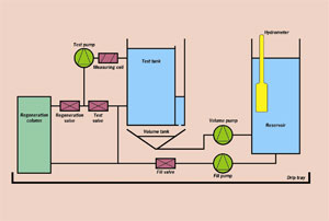
The CM60 is suitable for use as both an off-line (e.g. PCB goods-in) cleanliness process monitoring tool as well as a continuous ‘in-line' sample-based statistical process control (SPC) instrument used at the beginning of a production process or after wave soldering to detect unacceptable process drifts before they manifest as a major defect issue. It also features a novel volumetric testing cell that removes the need for users to have to calculate the surface area of assemblies under test (hence reducing test setup and cycle time) and can accommodate test pieces up to 600 x 550 x 60mm in size.
Because the CM60 is intended for factory floor operation, the machine is designed to be simple for a non-skilled operator to use. As such the only manual task required is to insert the test PCB or piece at the beginning of the test and remove it at the end. Once the tester is configured, all other test cycle operations are fully automated.
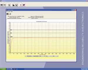
Test results are presented in a graphical format and can be used for further statistical analysis. The degree of contamination directly correlates to the likelihood of a board successfully soldering, or whether an assembly has been soldered at less-than-optimum process parameters. Moreover, results of the test can also indicate whether the assembly is likely to suffer a field failure as a result of exposure to conditions likely to promote the growth of reliability compromising dendrites or intermetallics.
"In an age where adherence to legislation, stringent process control, high throughput of quality products and low consumer tolerance of failures are conflicting pressures on manufacturing engineers, the Contaminometer is one reliable tool that can make the job easier," summarises Naisbitt.
About Ionic contamination testing
Ionic contamination testing – commonly referred to as ‘cleanliness testing' – has for over 40 years been used to measure the amount of ionic contamination (or ‘cleanliness level') present on PCBs, components and assemblies.
Ionic contamination testing is required as ionic residues remaining on both the PCB manufacturing process and the soldering process may affect the reliability of a finished assembly. In a humid operating environment and the presence of an electrical bias, ionic contaminants can cause problems such a shorting between conductors by electrolytic dendrite growth, corrosion that erodes the conductors themselves, or loss of insulation resistance.
The solution is to eliminate the ionic contaminants (as minimising the humidity or electrical bias in an operating environment is virtually impossible). In practice, it's impossible to completely remove all contaminants, so maximum threshold levels such as 0.2?g/cm2 NaCl equivalence are commonly accepted for modern densely packed assemblies.
Although flux residue is a very common source of ionic contamination, it is not the only source in the electronics assembly. Other sources include etching, plating, tinning or levelling residues, poor soldermasks, undercured permanent or temporary solder masks, dust, moisture, oil pollution from finger prints, component packaging materials, and machine maintenance oils (especially from wavesoldering conveyors).
About the Contaminometer
The Contaminometer has traditionally been employed in high reliability manufacturer facilities to diligently test occasional samples to ensure contamination is below the given threshold. But all that has changed with the advent of lead-free soldering. Lead-free soldering brings with it a dramatically narrowed process control window. Whereas previously, tin lead soldering offered a wide tolerance of the processing parameters, lead-free is much less forgiving and manufacturing engineers are searching for tools to help them maintain process equilibrium. One answer is the Contaminometer.
A Contaminometer measures ionic contamination by essentially immersing a sample in a test solution of 2-propanol and de-ionised water to dissolve the contaminants. The dissolved ionic substances cause a change in conductivity of the test solution; this change is precisely measured and converted into a contamination value expressed as ug/cm2 NaCl equivalence.
About the CM60
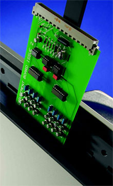
In operation, the CM60 (and the CM11 and CM12) achieves the above by automatically re-purifying a given volume of test solution each time a new test is run using a special regeneration or de-ionising cartridge that is easy to exchange. Electronic control is provided by a low voltage system enclosed in a separate, easily accessible cabinet.
The CM60 also utilises a solid gold measuring cell, ballistic amplifier and a vigorous pumping system to achieve superior measurement accuracy of than 0.005 mS/cm even at very low conductivity values. The CM60 has also been designed to avoid polarisation effects between electrodes as might occur when using DC test currents. Equally, error signals caused by both DC and AC currents are eliminated and high accuracy is ensured even at low conductivity values.
Automatic temperature compensation is incorporated in the electronic control system, using a thermistor in the test cell for temperature measurement. The Contaminometer software uses a complex algorithm to automatically compensate for ambient temperature, circuit volume and atmospheric absorption of iogenic gases. Temperature is monitored and all measurements are related to the international standard of 20 C.
The CM 60 operating software runs on Windows XP or Vista and features a user-friendly interface to guide operators through the test cycle. Test results include a pass/fail analysis and can be displayed in a 2-dimensional or 3-dimensional representation that can be rotated for ease of analysing the displayed data. The operating software is further designed to enable easy export of test results into other word processing and SPC software packages.
SOURCE: Gen3 Systems