
What's Your Real (or Imaginary) LCR IQ?
 LCR IQ?")
Take this quiz to test your knowledge of impedance measurements.
True or False:
- Impedance is comprised of Inductance, Capacitance and Resistance.
- Impedance is the total opposition a circuit provides to the flow of AC current at a specified frequency (i.e. AC resistance).
- Impedance is made up of ‘real' resistance and ‘imaginary' reactance.
- Reactance is calculated as 2pfL for an inductor and ½pfC for a capacitor.
- All devices can be represented by a series or parallel combination of resistance and reactance.
- Admittance, the reciprocal of Impedance, is often used instead of impedance in order to simply mathematical calculations.
- Conductance is the reciprocal of pure resistance, yet pure values don't actually exist.
- The dissipation factor (DF) is the ratio of the real part of impedance to the imaginary part, Q is its reciprocal.
- A low value of DF for a capacitor, or high value of Q for an inductor means that the component is nearly pure.
- All of these impedance parameters can be measured directly using an LCR Meter
Your Score:
8-10: Congrats, you're a ‘real' LCR Wizard! Complex Quantities Rule!
4-7: LCR is a necessary evil. ‘Imaginary' components exist to muddle the measurements.
0-3: You slept through Dr. Scott's class and could really give a flying lima bean about LCR!
For a little more depth of information on the subject of passive components, read on.
•Introduction
•Measurement Parameters
•Let's Talk About Measurement Techniques…
•Conclusion
Impedance is the basic electrical parameter used to characterize electronic circuits, components and materials. Impedance is the sum of alternating current oppositions (capacitive reactance, inductive reactance and resistance) by a circuit. It is represented by the symbol Z and is measured in ohms (W). So how do you get ohms out of complex quantities? A little imaginary math! Refer to the vector diagrams for a physical illustration of Impedance and its reciprocal parameter, Admittance.
In a pure DC world, Ohm's Law tells us that Resistance = R = V/I
But in the ‘real' AC world any LCR Wizard knows that the mixing of the following passive component potions will produce the complex quantity of Impedance…
Resistance plus j times Reactance equals Impedance
Abbracadabra! "POOF"! And there you have it! A magical value of Impedance (Z)!
Seriously, every circuit has inductive and capacitive components. Measuring L, C and R will only give you a more precise analysis of the electrical characteristics of the device under test (DUT). Capacitance and inductance cause the voltage and current to be out of phase. The phase shift can be drawn in vector form illustrating the impedance (Z), its real part (RS), its imaginary part (jXS) and the phase angle (q). All devices can be modeled as a real component (resistor) in series or parallel with a reactive component (capacitor or inductor). The subscript "s" or "p" denotes how the device will be modeled for a particular measurement. Impedances in series add, therefore the equivalent circuit for impedance would place RS and XS in series. To further analyze the electrical characteristics of your DUT, look at Admittance (Y) which is the reciprocal of Impedance (Z). Admittance is measured in siemens (S) and is comprised of ‘real' conductance (GP) and ‘imaginary' susceptance (BP) with a phase angle (f). Admittances in parallel add, therefore the equivalent circuit for admittance would place GP and BP in parallel.

Two other secondary parameters important to impedance measurements are the dissipation factor (DF) and quality factor (Q). The quantities DF and Q are useful as a measurement of the ‘purity' of a component or how close it is to being ideal (‘real') containing only resistance or reactance. DF is the ratio of the real part of impedance to the imaginary part. A low DF indicates that a capacitor is nearly pure. Q is the reciprocal of DF and is the ratio of the real part of admittance to the imaginary part. A high Q value indicates that an inductor is nearly pure. Conversely, a high DF or low Q value indicates that a resistance is nearly pure. Some sign conventions are necessary when discussing DF and Q. For capacitors and inductors DF and Q are considered positive as long as the real part of Z or Y is positive (as it will be for passive components). Note that transfer impedance of passive networks can exhibit negative real parts. For resistors, a common convention is to consider Q to be positive if the component is inductive (having a positive reactance) and to be negative if it is capacitive (having a negative reactance).
The DF and Q factors are independent of the configuration of the equivalent circuit used to represent an impedance measurement. These series and parallel equivalent circuits both have the same value of complex impedance at a single frequency, but at any other frequency their impedances will be different.
So how do you accurately measure impedance parameters to fully characterize your electrical device? Take a look at your LCR instrumentation. What is the measurement technique? What's the connection method? Can you test multiple parameters over a wide range of test frequencies and voltages? Does it provide Constant Source Impedance? How about auto-ranging or averaging capabilities? What kind of compensation does it provide? Can the instrument be remotely operated? Can the test results be saved internally or externally through a computer interface? Read on to find out if your current LCR instrumentation fully measures all parameters of passive components, precisely and expediently.
Let's Talk About LCR Measurement Techniques…
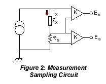
Digital signal generation and detection provides greater speed and accuracy of LCR measurements. As shown in Figure 2, carrying essentially the same current, the voltage across the DUT (Zx) and the voltage across the reference resistor (Rs) are measured. The voltage across Zx (= Ex) and the voltage across Rs (= Es) are sampled multiple times per cycle of the applied sine wave excitation. The real and imaginary components of Ex and Es are combined with the known characteristics of Rs to determine the apparent impedance of Zx. This circuitry and fast sampling rates, along with elaborate software driven control, can provide direct readout of all the impedance parameters previously discussed.
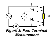
Four-Terminal Measurements are pretty much a given in obtaining accurate impedance measurements with today's LCR meters. One pair of leads applies the current (source) to the device while the other pair of leads measures (senses) the voltage across the device. This removes the series inductance and resistance error factor including contact resistance. It also removes the stray capacitance factor. Shielded coaxial cabling will reduce most mutual inductance that occurs between the current leads and the voltmeter leads. This four-terminal connection technique is widely known as a "Kelvin" connection.
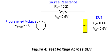
Test Voltage is one thing that is often overlooked when making impedance measurements with an LCR meter. The programmed test voltage is usually an open circuit voltage and not necessarily what the test device would see. The actual test voltage depends on the value of the measuring instrument's source impedance (Rs) and the impedance of the device being measured. For example; in Figure 4, if the test voltage is programmed for 1 volt, the instrument source impedance 100W and the impedance of the test device 100W, the voltage to the device is really only 0.5 volts. You can see that this is generally not a factor when measuring high impedance, where the value is much larger than the source impedance and the majority of the test voltage is applied directly to the device. For devices that are test signal level dependent, the most common way of dealing with this issue is to use a measuring instrument which employs a constant voltage or voltage leveling mode.
Auto Ranging on an impedance measuring instrument is intended to maintain maximum signal level and the highest signal–to–noise ratio for maximum measurement accuracy. In order to measure over wide impedance ranges an instrument must have several measurement ranges. The whole idea is to keep the measured impedance as close as possible to full scale on any given range. Perhaps most importantly, ranging is usually done automatically depending on the impedance of the test device, thus eliminating an improper selection by an operator resulting in erroneous measurement data.
Averaging is another way of improving instrument measurement accuracy, by reducing unwanted signals and effects of unwanted noise, but of course does require that some measurement speed be sacrificed. In an averaging mode many measurements are made and the average of these calculated for the final result. The more measurements averaged, the more the accuracy is enhanced.
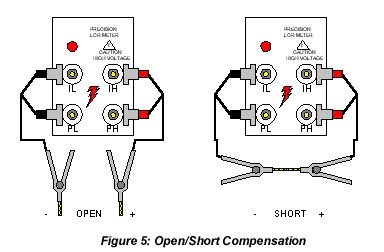
Open/Short Compensation reduces the effects from error sources between the DUT and the calibrated connection to the measuring instrument. Compensation will ensure the best measurement accuracy possible on a device at the selected test conditions. The traditional open/short routine measures the stray admittance (YOPEN) and residual impedance (ZSHORT) of the test cable(s) to remove these quantities from the actual measured DUT value. The OPEN routine determines the correction that the instrument applies to high impedance measurements and the SHORT routine determines the correction necessary for low impedance measurements. Figure 4 illustrates the connection to the LCR Meter for open & short compensation using the four-terminal connection.
Load Correction is a compensation technique which uses a load whose impedance is accurately known, and applies a correction to measurements of similar components to substantially improve measurement accuracy. The purpose of this being to correct for non linearity of the measuring instrument, test fixture or lead effects, all of which may be repeatable and thus can be added or subtracted each time a similar measurement is made. Load correction is only as good as the known accuracy and/or traceability of the load used in determining the correction.
Recent trends in electronic component manufacturing have placed increased demands on LCR instrumentation. Devices are moving to smaller packages, used at higher frequencies, and emphasis towards the more perfect component. All this creates new challenges in making contact which devices and measuring them with more speed and accuracy. Automation and features leading to more reliable testing is the way of future LCR meters and test techniques. An understanding of test parameters and measurement techniques goes a long way in producing useful results.
About the Author
Tracey Gilpin has been with QuadTech, Inc. for two years in a technical writing capacity on several new products. Previous to her employment at QuadTech, Tracey assumed various roles in quality and product engineering as well as technical writing in the Defense Electronics Industry. Tracey holds a BSEE degree from the University of Massachusetts, Amherst. She can be contacted at tgilpin@quadtech.com